
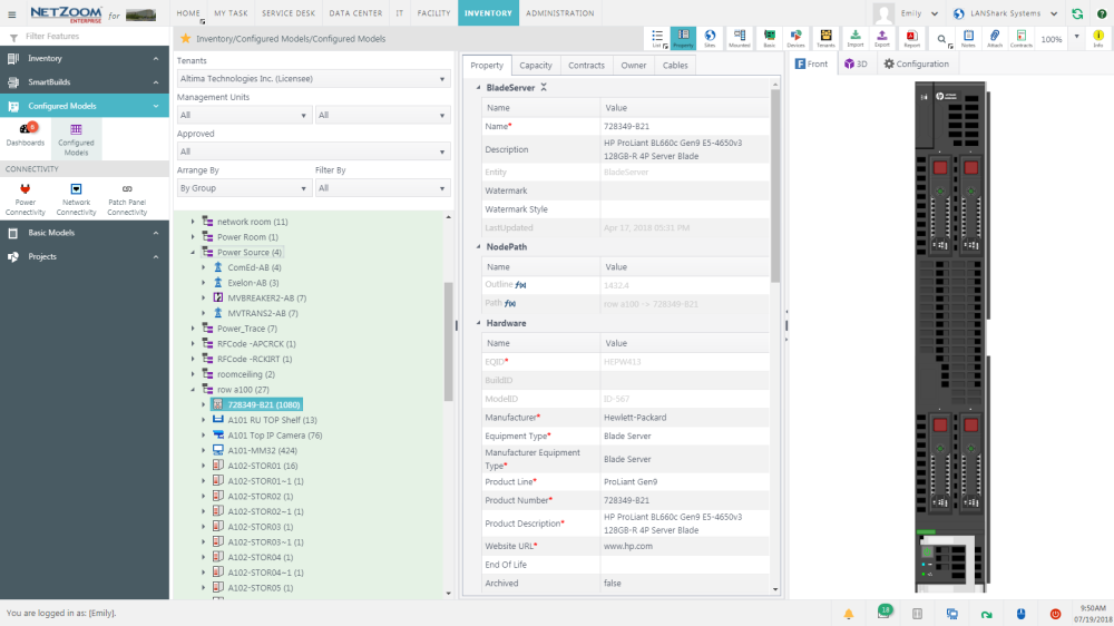
Configured Models
Configured Models are larger devices that can operate on their own, without needing to be installed in another device model. Configured Models are usually rack mountable, though there are some that are not. Configured models can be added to inventory alone or used as part of a SmartBuild. Power and Network Connectivity internal to a configured model can be tracked and managed. Configured Models require an Asset ID when approving as an inventory item.
Configured models can be configured using basic models or other configured models.
Creating Configured Models
Configured models can be created and managed using the Configured Models feature.
Feature Path: Inventory/Configured Models/Configured Models
Adding a Configured Model from the Device Library
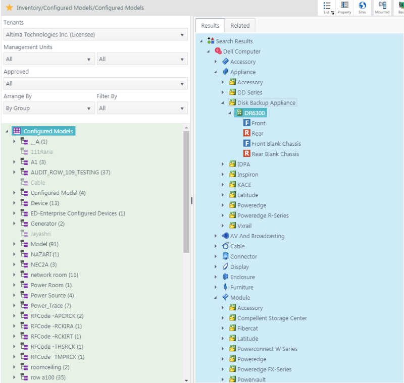
- To add an instance of a configured model from the device library, click QA: Devices. The Search pane and the Results pane will appear.
- Search for the device shape you want to add in the Search pane.
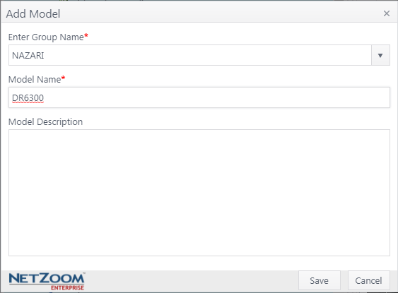
- Select the shape you want to add from the Results pane and drag-and-drop it to the desired group in the Infrastructure Explorer pane. The Add Model form will pop up.
- Choose a group for the model from the Enter Group Name combo box. Entering a new group name will create a new group.
- Provide a name and description for the configured model.
- Click the [SAVE] button. A copy of the selected model will be added from the Device Library to the selected group in Configured Models.
Configuring a Model
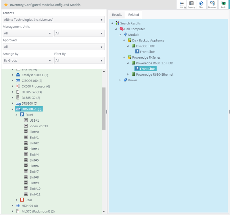
Shapes can be added to configured models from the NetZoom Device Library or Basic Models. This can be done by dragging and dropping shapes into the slots you want them to be added to.
- Select and expand the model you want to configure in the Infrastructure Explorer pane. The slots will be displayed.
- Select an available slot in the model. If the equipment occupies more than one slot, make sure the appropriate number of slots are available on either side before mounting the equipment.
- Search the NetZoom Device Library or Basic Models for the shape you want to add to the model. If your model has sub-models and the required device models do not exist, NetZoom will automatically generate and approve the missing basic models or configured models for you.
- Expand and select the desired shape view from the search results.
- Drag-and-drop the desired view of the equipment directly into the slot. This will insert the equipment automatically.
- Provide a Name and Description for the equipment and click Add.
Approving a Configured Model
- To approve a configured model, right-click on the model you want to approve in the Infrastructure Explorer pane.
- Click [APPROVE]. The device will be approved and can be used in the inventory.
- Right-clicking on a group and clicking [APPROVE] will approve all models in that group.
Emptying Slots
Should you need to empty the slots of your configured model quickly, NetZoom provides the Empty Slots right-click action.
- To empty the slots of a configured model, right click on the model in its inventory store. Be aware: the model must be unapproved to use this action.
- Click the [EMPTY SLOTS]
 action. All slots in the configured model that have devices installed in them will be emptied, leaving you with a clean build of the model.
Unapproving a Configured Model
- To unapprove a configured model, right-click on the model you want to un-approve in the Infrastructure Explorer pane.
- Click [UNAPPROVE]. You cannot unapprove models that are in use.
- Right-clicking on a group and clicking [UNAPPROVE] will unapprove all models in that group that are not in use.
Note: To prevent additional inventory items from being created for an approved model, set the Archived property to True.
Cloning a Configured Model
- To clone a configured model, right-click the model you want to clone and click [CLONE]. The Clone Device form will pop up.
- Choose a group for the model from the Enter Group Name combo box. Entering a new group name will create a new group.
- Enter a name and description for the model. This must be different than the parent model.
- Click the [SAVE] button. The model will be cloned and added to the Infrastructure Explorer.
Deleting a Configured Model
- To delete a configured model, right-click the model you want to delete. You cannot delete models that are approved.
- Click [DELETE]. The configured model will be deleted.
- Right-click on a group and click [Delete All Unapproved Devices] to delete all models in that group that are not approved.
- Right-clicking on a group and clicking [Delete Group] will only delete the group if it is empty.
Exporting Configured Models to an Excel spreadsheet
- Select a Configured Model or Group.
- Click QA: Export. The Export form will pop up.
- Select Node Hierarchy or Update Property. Node Hierarchy exports model configurations, while Update Property exports model properties.
- Click the [EXPORT] button. The configured models will be exported as an Excel spreadsheet
Importing Configured Models from an Excel spreadsheet
- Select a Configured Model Group.
- Click QA: Import. The Import form will pop up.
- Select Node Hierarchy or Update Property. Node Hierarchy adds new models, while Update Property updates existing models. The Verify and Import form will pop up.
- Click the […] button to open a search form.
- Select the spreadsheet containing your configured models and click the [OPEN] button.
- Click the [SAVE] button when finished. Your configured models will be imported.
Note: For more information on formatting this spreadsheet, see [import documentation].
Available Quick Actions
- View Model Usage in Sites
- Slots and Ports
- Basic Models
- Library
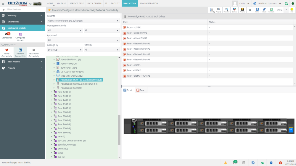
Adding Connectivity to a Configured Model
Connectivity internal to a configured model can be mapped before the device is added to Inventory. Use the Connectivity Wizard to map Power and Network Connections in Power Connectivity and Network Connectivity features, respectively. When a device is selected in the Infrastructure Explorer, that device will appear in the Connectivity Wizard with all its ports listed. Patch Panels cannot be configured using these features.
Feature Path: Inventory/Configured Models/Connectivity/Power Connectivity
Feature Path: Inventory/Configured Models/Connectivity/Network Connectivity
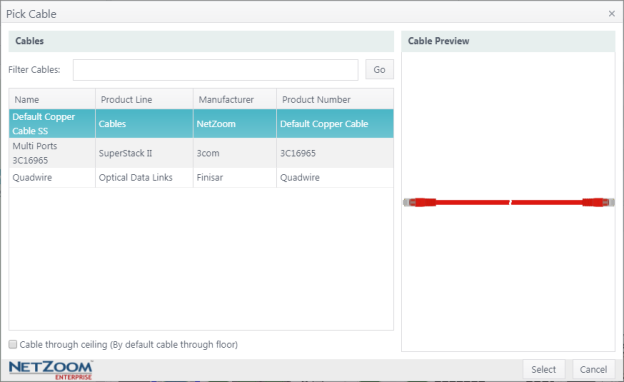
Attaching a Cable to a Device
- To attach a cable to a device in the Connectivity Wizard, select the port on the device you want to connect the cable to.
- Click the
 icon. The Pick Cable form will pop up. This lists cables you have added to NetZoom. Cables can be added to NetZoom as Basic Models.
 - Select the cable you want to attach to the device.
- Check [X] cable through ceiling if applicable.
- Click the [SELECT] button. The cable will be attached to the device.
Breaking a Connection
- To break a connection, select one of the connected ports in the Connectivity Wizard.
- Click the
 icon. The selected port will be disconnected.
Note: When breaking one-to-many connections, click the disconnect icon on the single-port side to disconnect only that port, click the disconnect icon on the multi-port side to disconnect all connected ports.
Removing a Cable from a Device
- To remove a cable from a device, select the port you want to remove a cable from in the Connectivity Wizard.
- Click the
 icon. The cable will be removed.
Blocking and Unblocking Ports
- To block or unblock a port, select the port you want to block or unblock in the Connectivity Wizard.
- Click the
 icon. If the port is unblocked, it will be blocked, or vice versa.
Available Quick Actions
- List View
- Show Properties
- Slots and Ports
- Library
- Tenants
- Reports
- Search
- Add Notes
- Attach a File
- Contracts
- Zoom
- Quick Help
Configuring Patch Panel Connectivity
Connectivity internal to a patch panel can be configured using the Patch Panel Connectivity feature. This allows you to configure the internal connectivity between the front and rear ports of the patch panel before adding it to your inventory. When a patch panel is selected in the Infrastructure Explorer, the front and rear of the patch panel will automatically be displayed in the Connectivity Wizard.
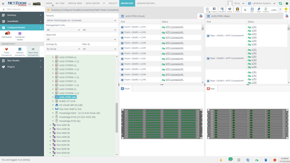
Connecting Front and Rear ports
- To map the internal patch panel connectivity of a patch panel, select the patch panel in the Infrastructure Explorer. The front and rear ports of the patch panel will be displayed.
- Select one port on the front and one port on the rear in the Connectivity Wizard.
- Click the
 icon. The selected ports will be connected.
 - Repeat steps 2 and 3 as needed to map the internal patch panel connectivity.
Breaking a Connection
- To break a connection, select one of the connected ports in the Connectivity Wizard.
- Click the
 icon. The selected port will be disconnected.
Note: When breaking one-to-many connections, click the disconnect icon on the single-port side to disconnect only that port, click the disconnect icon on the multi-port side to disconnect all connected ports.
Disconnecting All Ports
To disconnect all ports in a patch panel, click the  icon. All connections made will be broken.
Available Quick Actions
Last Updated: Tuesday, December 22, 2020
NetZoom, Inc.